Improved Efficiency of Linear Actuator Design
Linear Actuator Design
Knowing how to develop a durable linear actuator through detailed lead screw design is vital. One important aspect of designing a linear actuator is the lead screw. Electric linear actuators consist of three key mechanical components: lead screw and nut, gear train, and the electric motor. Within this article we will be focusing on how to select the appropriate lead screw to design your linear actuator.
In terms of electric linear actuators, most of the time the lead screw must be non-back driving. The normal operation of a linear actuator is for a piston type part to push outward form the actuators housing. Whether the piston must push or pull a load, the system requires outward movement and then retraction. Linear motor actuators are self-locking devices because they are often in a non-continuous cycle. Depending on the application a linear actuator may only be driven two-thirds of its full stroke length. Regardless of the distance traveled, the piston and lead screw must be able to lock the load when there’s no electric current to the motor.
What is Back Driving?
Back driving is the result of the load pushing against the linear actuators piston. This load on the piston works back against the lead screw and gear train, creating a rotating motion which in turn rotates the motor. If a system is back drivable, then it will not be able to retrain a load and drift back to its home position.
Best Design Practices
Linear Actuator Dynamic Formulas
When starting the analysis of the lead screw within the electric linear actuator, you must first establish the working loads on the system. The University of North Carolina Charlotte has written an informative article on ball screw design, covering this topic as well. The image shown in Figure 1: Rotary to Linear Motion represents the conversion of lead screw rotary motion to lead screw nut linear motion.
Drive Torque and Rotational Speed
The first step to analyzing linear actuators lead screw is to begin with calculating the rotational speed and drive torque. The basic requirements given for a lead screw actuator should include the load to be moved and the time of which it must be moved. Understanding those input values will allow a starting point for lead screw sizing. Formulas Equation 1 and Equation 2 below, are simple calculations to begin the analysis process.
Figure 1: Rotary to Linear Motion

Drive Torque Formula:
T = Drive Torque (in-lb)
F = Thrust load or linear load (lbf)
Eff. = Lead screw efficiency
Equation 1

Rotational Speed Formula:
N = Rotational speed (rpm)
L = Lead screw lead (in)
V = Linear speed (in/min)
Equation 2

Lead Screw Efficiency
The efficiency of an electric linear actuator must be a top consideration because it tells you how well the actuator converts motor torque into linear motion. Linear actuators typically transmit this motion through lead screw and lead screw nut arrangements. This results in sliding motion that experiences losses due to friction. Working speeds and loads must be evaluated to understand the heat generation during the max duty cycle conditions. Lead screw efficiencies can be calculated from the formula in Equation 3. Testing should be performed to best evaluate operating efficiency.
Lead Screw Efficiency
Eff. = Efficiency
Θ = Lead Screw Helix Angle
f = Coefficient of Friction
Equation 3

Lead Screw Back Driving
A general rule of thumb is lead screws with efficiencies greater than 50% will drive. Back driving becomes feasible with high efficiency lead screws because of less frictional losses. So if a non-back driving system is required like in our linear actuators, then target an efficiency of less than 50%. Another quick method is to compare the lead screws lead and diameter. If the lead is than 1/3 of the diameter then back driving will not occur.
Another method of locking an actuator is to install a load holding brake. There are various load brake on the market then can be worked into your linear actuator. This of course drives an additional adding weight, cost and complexity to the assembly and analysis. But a physical brake may be the best solution based on your electric actuators’ efficiency needs and speed requirements.
How do you Improve Linear Actuators Efficiency?
Linear actuators have three mechanical systems that experience efficiency losses, which include the gear train, lead screw and motor. In this article we are going to focus on the lead screws efficiency because this is where some of the highest losses can be experienced. Helical gear and spur gear train efficiencies can also be of concern but contribute to a small margin in comparison to the lead screw.
Two easy methods to improve the efficiency of a lead screw system are:
- Increase the lead
- Increase the helix angle
These two dimensions of a lead screw are proportionally related to each other, so increasing the lead will also increase the helix angle. See Example 1 and Example 2 to better understand how to improve the efficiency within your electric linear actuator.
Helix Angle Formula:
L = Screw Lead
PD = Pitch Diameter
Θ = Lead Screw Helix Angle
Equation 4

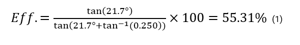
Example 1
Find the lead screws efficiency.
Given data:
Screw Diameter: 0.200”
Screw Lead: 0.250”
Material: Acetal
Material Dynamic Coefficient of Friction: 0.250
Step 1 – Solve for the lead screws angle

Step 2 – Solve for the efficiency
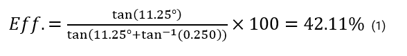
Example 2
Find the lead screws efficiency.
Given data:
Screw Diameter: 0.200”
Screw Lead: 0.125”
Material: Acetal
Material Dynamic Coefficient of Friction: 0.250
Step 1 – Solve for the lead screws helix angle

Step 2 – Solve for the efficiency.
Lead Screw Critical Speed
What do you mean by critical speed?
The critical speed of a lead screw is the rotational speed which causes the shaft to vibrate at its natural frequency. This frequency is generated by the dynamic forces acting against the lead screw. This effect can even cause resonant vibrations through the entire machine and machines hardware. This can be very damaging to a linear actuator, causing catastrophic failures of the lead screw or other attached hardware. Critical speeds are something to be concerned about when operating at high speeds, but as a general best practice we always want to evaluate our critical speeds margin of safety. The rotational speed of the lead screw is limited to 80% of the critical speed. Meaning, calculate your critical speed and then take 80% of that value to establish your limit (e.g. 2500 rpm x .80 = 2000 rpm). This 80% margin helps account for manufacturing tolerances and mounting misalignments.
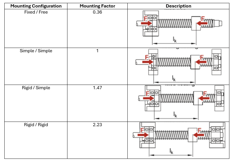
Lead Screw Mounting Configurations
How the linear actuators lead screw is mounted is another critical design point based upon the loading. The mounting configuration also allows for a higher allowable rotational speed and can reduce the amount of total misalignment. As the mounting factor increases as shown in Table 1: Lead Screw Mounting Configurations, so does the allowable critical speed of the lead screw, as shown in Equation 3.
Table 1: Lead Screw Mounting Configurations
Critical speed Formula:
Cs = Critical speed
MF = Mounting factor
L = Screw lead (in)
DR= Screw Root diameter (in)
Equation 5

Lead Screw Buckling
Oversizing the lead screw is a costly oversight, especially when weight and product pricing are of high value. We here at Covalo find it imperative to evaluate all structural aspects of the lead screws selected for our actuators.
All electric linear actuators are exposed to either a compressive load or tensile load. Evaluating the compressive load on the lead screw can be of high importance to reduce lead screw size and avoid a catastrophic failure. Lead screw manufacturers recommend establishing a factor of safety of 2.0 for the maximum buckling load. Always consult your manufacturer for their applied mounting factors. Some manufacturers will incorporate the 2.0 safety factor within their mounting factor. The values shown in Table 1: Lead Screw Mounting Configurations are for preliminary design only. Final analysis should be done with the factors supplied by your lead screw manufacturer. The calculation to evaluate compressive buckling loads of a lead screw can be found within Equation 4.
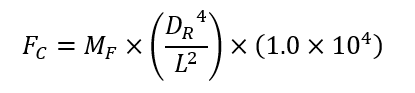
Buckling Load Formula:
FC= Maximum compressive load (lbf)
DR= Screw Root diameter (in)
MF = Mounting factor (in)
L = Unsupported screw length (in)
Equation 6
Effectively designing a linear actuator is not an easy task. Dependent upon the application, there are various design conditions that must be evaluated. Whether it be the lead screw design, gear train, environmental conditions, service life or electrical system consideration must be taken for all of these requirements. Covalo industries has built a reputation for designing mechanical systems like electrical actuators. This has come from years of industry experience and exposure to different applications. If you have an application which requires a durable solution, feel free to see our website page on linear actuators and contact us about your design.