Fundamentals of Gearbox Design
Fundamentals of Gearbox Design
Gearbox design is a complex engineering process that involves selecting and arranging gears to transmit power from one rotating component (like a motor or engine) to another. Gearboxes are widely used in mechanical systems to alter the speed, torque, and direction of motion. The design of a gearbox must consider factors such as load capacity, efficiency, size, weight, material selection, and the intended application (e.g., automotive, industrial machinery, or aerospace). Covalo Industries specializes in the design of custom gearboxes and understands how to meet the demands of these complex requirements.
When having a general understanding of the complexity that’s involved in the operation of a gearbox, it is recommended to break the gearbox down into subsystems. This is the method Covalo Industries finds the most useful because it creates a step process through the system. By doing so the designer can lay out the systems requirements and then begin working through each layer.
Here’s an overview of the key aspects of gearbox design:
Define Requirements
Due to the extent of developing a gearbox, the full thorough process would be much longer than what can be spelled out in this article. This article will take you through a high-level view of things which must be considered. Covalo Industries is passionate about developing gear systems and is always interested in supporting your application. Feel free to send us an inquiry here, so we can help you get started.
Begin developing the gearbox by defining all requirements essential to operation. To capture all requirements Covalo uses an acronym they refer to as NEEAMP. This stands for noise, energy, environmental, assembly, material and physical. These are the categories which will pave the way in defining all requirements for the custom gearbox.
Here is a breakdown of some NEEAMP characteristics:
- Noise
- Vibrations
- Transmission error
- Critical speeds
- Alignments
- Balancing
- Energy
- Power transmission
- Heat transfer
- Pressure
- Environmental
- Corrosion
- Moisture
- Temperatures
- Debris
- Assembly
- DFM
- Fits
- Envelope Sizing
- Assembly access
- Material
- Material type
- Core Hardness
- Case Hardness
- Surface treatment
- Physical
- Gear ratios
- Speed and torque transmission
- Application
- Sizing
Now that the system characterizations are broken down, some specifics need to be highlighted to begin the development. These are critical to begin designing the gearbox because they will dictate sizing of hardware.
- Power Transmission: Understand the power that needs to be transmitted, typically measured in horsepower (hp) or kilowatts (kW). This will determine the size and strength of the gears.
- Speed and Torque: The gearbox design needs to account for the input and output speeds (RPM) and the torque required at the output.
- Gear Ratio: The ratio of the speed of the input gear to the speed of the output gear. It defines how much the speed is reduced or increased.
- Application: Different applications (e.g., automotive, industrial machinery, robotics) require different types of gearboxes (e.g., manual, automatic, planetary, worm gear).
Duty Cycle
Often a customer will only supply a singular set of input requirements (speed, torque/HP). These of course can be used to develop a gearbox but do not capture the full operating picture. Development of a custom gearbox requires understanding operating times under different conditions. This is also referred to as cycle of the motor and given the name of “duty cycle” For example, having the peak load conditions is important but may not be as damaging as medium load conditions that run for 75% of the time. It is recommended to ask the customer to supply a motor duty cycle or work with the customer to generate a duty cycle for gearbox design. The more variations provided for the operating envelope the better the gearbox will be designed. Here is an excellent resource by KEB America on understanding a duty cycle.
Choose the Gear Types
There are several types of gears to choose from, depending on the application:
- Spur Gears: Simple gears with straight teeth. Best for low-speed, high-torque applications.
- Helical Gears: Teeth are cut at an angle, allowing for smoother and quieter operation. Used for higher-speed applications.
- Bevel Gears: Used for transmitting power at a 90° angle.
- Worm Gears: A gear arrangement where a worm (a gear with a screw-like thread) meshes with a worm wheel, providing high reduction ratios and compact design.
- Rack and Pinion: Used to convert rotational motion into linear motion.
Determine Gear Ratio
The gear ratio is crucial for controlling the speed and torque at the output shaft. The formula for calculating the ratio will differ depending on the type of gearbox arrangement. The formula for a worm gearbox is different for that of a epicyclic gearbox.
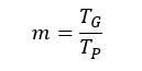
Equation 1: Single stage gear ratio
Equation 1 represents a single stage gearbox and would be ideal when designing a worm gearbox or a compound gear train. A note to keep in mind is a higher gear ratio provides more torque but reduces speed, while a lower ratio gives higher speed with less torque.

Equation 2: Triple Stage gear ratio
Equation 2 would be applied for a multistage compound gearbox. The three stages represent the reduction between each set of shafts. Another important aspect to keep in mind is maintaining the size and weight of the gearbox.
Gearbox reduction Example
For example, a total reduction ratio of 15:1 is desired to reduce the speed of 3000 rpm.

Equation 3: Speed reduction
With this information two factors are known, the input speed and what is required for the output speed. The next phase of developing the gear train is keeping each gear as small as possible with still meeting the speed and strength requirements. This can be achieved for a gearbox by taking the cube root of the gear ratio as shown in equation 4. The cube root is being used because this example is a three-stage gear reduction.

Equation 4: Ratio reduction formula
The value produced by equation 4 should be the targeted gear ratio between each of the three stages. Given it is not a whole number the value may need to be rounded up or down depending upon the output speed requirements. If a specific stage must be adjusted to a larger or smaller ratio, that is ok but this serves as a good starting point in the development. Following this procedure will allow for having the same gears in each ratio, which will mean similar shafting, bearings and mounting methods.

Material and Component Selection:
Material Selection
All hardware within the gearbox must be evaluated closely for proper material utilization. This would include the type of material, core hardness and case hardness if needed for all parts. Many gearboxes experience failure due to fatigue, so it is important to understand the material properties under the specific operating conditions. Most companies spend millions of dollars to internally test and characterize materials for their application needs. General material properties can be found within their AISI specifications, but if your application requires operating at higher temperature ranges it is highly recommended to perform additional testing.
Each component making up the gearbox will have its own material requirements, from aluminum housings to tool steel bearings, medium carbon steel for shafts and gears. The various selection of materials is extensive and for that diligence must be taken to properly select each material
Here are some common gear materials used:
- Steel: Widely used for high-strength and durability.
- Alloys: Can be used for lightweight or high-performance applications, like aerospace.
- Bronze: Often used in worm gears due to its wear resistance.
- Plastic: Used for lower-load applications or where noise reduction is critical.
Bearings
Bearings support the shafts and allow smooth rotation of the gears. The design must account for bearing type (e.g., roller bearings, ball bearings) and shaft materials for optimal load handling and durability. The type of bearings used in the gearbox will depend on the application of the gearbox and the type of gears within the unit. Bearings must allow rotation of the drive shafts but also manage the loads within the gearbox.

Figure 1: High precision SKF bearing
All gears transmit loads different which require different bearing types and arrangements. For example, straight cut gears (spur gears) only transmit loads radially and tangentially to the tooth. But the loads of a helical gear include the same as a spur gear, with the addition of an axial load on the shaft. If the proper type of bearing is not selected, then the bearing will not meet life or can even cause a catastrophic failure.

Figure 2: Gearbox roller bearings
Shafts
Shafts assist in transmitting the load throughout the gearbox. They also retrain the gears and allow them to rotate on a precise axis. Proper shaft sizing, material selection, localized case hardening are all critical for successful design. Thorough analysis must be conducted to proper size all critical regions of the shafts within the gearbox. Typically shafts must contain machined features like corner radii, key slots and threads. These kinds of features can be hot spots when it comes to fatigue failure with the gearbox.

Figure 3: Epicyclic gearbox shaft
Hardware like shafts can also quickly increase the overprice of the gearbox because of their high precision nature. It’s important to find a balance of precision and economic manufacturing. Shaft design is an ideal time to apply statistical analysis to understand the risk of failure to reduce the need for expensive machining tolerances.
Lubrication
Proper lubrication is essential to minimize friction and wear. The lubrication type (oil or grease) depends on the gearbox type and application. Lubrication methods can include splash lubrication, forced lubrication, or oil bath systems. The details involved in designing a proper lubrication system are beyond the scope of this article. This article is to only provide some insight on what types of lubrication systems exist. In the near future an article will be written on gearbox lubrication systems and linked into this section. If you’re interested in learning more now please contact Covalo Industries here to tell us about your application.
Seals
Seals are essential to retaining lubrication with the gearbox. When a gearbox is under operation it begins to produce large amounts of heat. The heat generation within the gearbox affects the viscosity of the lubrication and as a result thinning effects occur. This is an ideal time for a gearbox to begin leaking during operation. Seals are necessary to dam the oil in regions which experience thermal expansion, to prevent loss of lubrication. Running a gearbox without the proper amount of lubrication guarantees the system will not meet life. Along with keeping oil in the gearbox seals also serve as a barrier against foreign material to enter. Materials like dirt and dust entering the gearbox can be catastrophic to the lubrication system, which in turn will penetrate bearings and gear interfaces increasing heat generation and accelerating wear.

Figure 4: Transmission Seal Leakage
Some other factors to keep in mind:
Design Efficiency and Safety
- Efficiency: Gearboxes should be designed to minimize energy losses (mainly from friction and heat). The choice of gear materials and the correct mesh alignment of gears can optimize efficiency.
- Safety Factors: Gearbox designs must ensure that gears, shafts, and other components can handle maximum load conditions without failure. Safety margins are typically built into the design to account for unexpected stress.
Noise and Vibration Control
Reducing noise and vibration is critical, especially in consumer products (e.g., automotive gearboxes). This can be achieved through:
- Proper tooth geometry (e.g., helical gears instead of spur gears)
- Balancing of components
- Vibration damping materials
Simulation and Testing
Before finalizing the design, simulations (using software like CAD or FEA – Finite Element Analysis) are used to analyze the gearbox’s performance, including stress, strain, temperature, and wear. Prototype testing and adjustments are usually performed after the initial design phase to ensure the gearbox performs as expected under real-world conditions.
Types of Gearboxes
- Manual Gearbox: Common in cars, this type allows the driver to manually change gears.
Automatic Gearbox: Uses hydraulics and electronics to automatically shift gears based on speed and load. - Planetary Gearbox: Compact, with high torque and efficiency, often used in automotive transmissions and heavy machinery.
- CVT (Continuously Variable Transmission): Provides an infinite range of gear ratios, commonly used in certain types of cars and scooters.
Conclusion
A well-designed gearbox must meet specific performance requirements and be built to handle the expected loads and environmental conditions. The process requires a careful balance of efficiency, strength, weight, noise, and cost. Each decision made during the design phase (such as gear type, material, lubrication, and safety considerations) can greatly affect the final product’s reliability, efficiency, and lifespan.