Gear Mesh Interference
Successful spur gear design begins with the designer evaluating multiple critical attributes of the gear system, with focusing special attention on preventing gear mesh interference. One of the most critical requirements must be an interference-free gear mesh.
Vitally, all gear designs rely on interference-free gear mesh. This is so the gears can meet the life expectancy of the desired application. Due to the complexity of gear systems, there is not one simple solution to designing a robust gear train with zero interference. Instead, there are multiple steps which all need to be considered and taken. Below, various methods of designing gears to a zero mesh condition are discussed and explained.
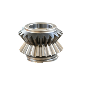
Figure 1. Straight Tooth Bevel Gear
As design engineers, it is critical to understand the quality of the gear system, and as such, the quality of the gear system will only be as good as the quality of the finished machined part. It is our top recommendation to always source parts to qualified gear shops, who have the appropriate equipment to machine and inspect your parts. Luckily, this article will give you an excellent gear design outline to follow. Continue reading to learn multiple gear design factors, and how to achieve a top working condition for your gear reducer.
What is Interference in Involute Gear Mesh?
Let us start off by defining gear mesh interference in involute gears. Gear interference is the act of when the involute portion of one tooth contacts the mating gear tooth, the non-involute section (below the base circle). This causes a mechanical wear condition, hence the term, interference.
The involute surface and tooth’s edge, dig into the mating gear tooth. This involute gear interference is a form of abrasive mechanical wear and can be detrimental to the life of a gear reducer. There are many basic gear systems to utilize for reducing or increasing speed and torque outputs which often experience gear mesh interference. Some of them are: rack and pinion, spur gears, planetary gear reducers, and helical gears. One of the most common gear systems which will experience mesh interference are rack and pinions, or pinion gears. The non-involute profile of the pinion rack tooth reduces the conjugate motion, making interference more likely to occur. Even though rack and pinion systems are simple in their mechanical nature, close evaluation must be taken to avoid an interference condition.
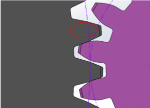
Figure 2. Mesh Interference
How Do You Prevent Gear Mesh Interference?
There are multiple factors that can cause gear mesh interference in a gearbox. From custom addendums/dedendum sizing, center to center distance variation, backlash, and improper tip/edge reliefs, gear mesh interference is one of the most probable causes for gear failures. Below we will outline each concern, and a possible solution for designing a zero interference planetary gearbox and gear system.
Gear System Ratios
A common cause for gear mesh interference in gears is high gear ratios. Often, gear mesh interference is seen in single stage gear trains. Designing a single stage spur gear mesh over 10:1 is not best practice if a designer is seeking to avoid involute gear interference. This is a common occurrence with spur gears and helical gears. The large contrast in size between the pinion and gear affects the difference between the base circles and tooth count. This causes issues in the timing of the gears during rolling mesh.
To reduce this occurrence, designing for closer tooth counts on two mating spur gears or helical gears will decrease the likeness for gear mesh interference. This is the reason why larger gear ratios should be divided into multiple stage gear reducers.
For example, a 10:1 gear ratio can be designed into two stages, where each stage possesses a 3.2:1 ratio. A lower gear ratio, like a 3.2:1 will allow for closer sized pitch diameters and tooth counts, reducing the chances of tooth tip undercutting on the mating gear. This of course is only an example of where to begin with each stage’s ratio.
We understand this is not always possible when designing a complex gearbox. Knowing that, we recommend starting at an equal ratio, working out from there by trying to keep each ratio below 7:1.
As a best practice, gears with ratios over 10:1 should be made into multiple stage gear reducers if the application allows. This design consideration will aid in preventing tooth mesh interference, along with additional functional benefits.
If the gear system has restraints which force a ratio greater than 10:1, the mathematical formulas demonstrated below can be used to find the most effective tooth count for the pinion and gear:
Gear Involute Interference Formulas
Formula 1:


Example:
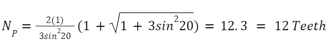
Explanation: If you’re looking to design a gear mesh using a 20 degree pressure angle, 12 teeth on both the pinion and gear will provide a zero involute gear interference. This is only the case when your design is a 1:1 ratio. This could be ideal when incorporating an idler gear, which doesn’t need to transmit load or change the speed.
Formula 2:
If your gear reducer requires a change in speed or transmitted load, where your gear is larger than your pinion. Use the following formula to have a zero interference condition:


Example:
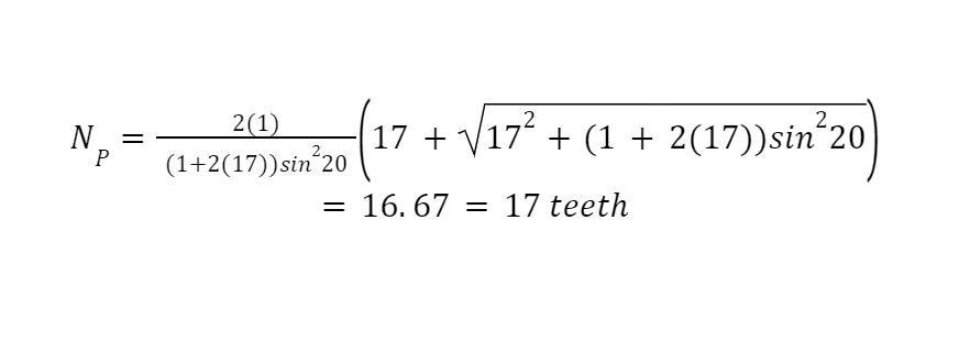
Explanation: This demonstrates what should be done in the case where a single stage gear reducer is needed and a ratio above 10:1 is necessary due to the design constraints. Based on the problem above 17 teeth would be the required tooth count on the pinion, if a 17:1 ratio was required. This is for a 20 degree pressure angle.
Formula 3:
In this case, a specific tooth count is required on a pinion. Use the following formula to find the number of on the gear to have an interference-free condition:

Example:
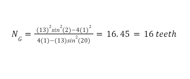
Explanation: Your design would allow a gear with 16 teeth max to mesh interference-free with the 13 tooth pinion. This example is using a 20 degree pressure angle but not incorporating the gear ratio as the two examples above.
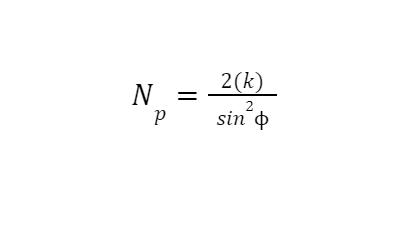
Formula 4:
This final formula calculates the smallest amount of teeth on a pinion, which can roll with a rack gear interference-free.
Example:
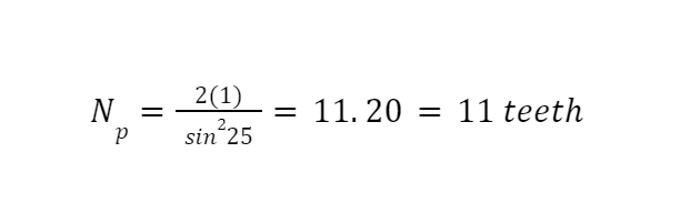
This final example, above, calculates the smallest amount of teeth which can accommodate a rack and pinion with zero involute gear interference.
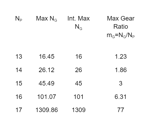
Formula 1 & 2 References:
Here are some useful values derived from Formula 1 and 2. These values are for a 20 degree pressure angle gear with full depth teeth:
Pressure Angle in Gear Interference
Pressure angle selection is integral to involute gear interference reduction. Using a larger pressure angle (25 degrees), derives a smaller base circle for generating the tooth profile. As the pressure angle rises, the tooth strength of the working gears does too. The smaller the base circle of your gear equates to a larger percentage of the tooth containing the involute profile. The involute profile is responsible for the conjugate motion of meshing teeth.
Though, designing gears with a 25 degree pressure angle can potentially have negative effects to be aware of. While serving to reduce mesh interference, this pressure angle will generate broader amounts of frictional forces, increasing bearing loads and decreasing the contact ratio. This should always be closely evaluated by the application of the gear reducer.
Tooth Tip Edge Reliefs
One of the simpler methods to reduce or eliminate involute gear interference is the proper usage of top land edge relief. Relief tip modification is important for reducing contact shock between teeth during transitions. There is no software to aid in the exact size of this tip radius, so both knowledge/trial and error are necessary. Figure 3 below from Gear Technology Magazine, displays the benefit of applying the tip relief versus a gear tooth without the relief. Without having a tip relief, the gear teeth become volatile to crack propagation, increased vibration, noise and surface scratches.
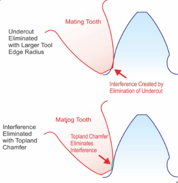
Figure 4. Top land with a radius
Figure 4 illustrates how this feature should be called out on a gear drawing (you can also add a detailed view of the gear tooth). Utilizing a maximum classification for the edge break/radii is the proper method because if the radii becomes oversized it can affect the meshing of the gear system, by reducing the percentage of gear face in contact. As we can see from Figure 4, undercutting this section of the tooth eliminates the area of contact with the mating gear. This will make for a non-uniform load distribution, which will reduce reliability performance in multiple areas of the gear reducer.

Figure 5. gear drawing notes with note #10 describing tip edge break to be used
Gear Tooth Undercutting
The final method of gear designing for an interference-free condition in this article, will be the involute tooth undercut. It must be known, this is not an ideal method or best practice to eliminate interference. All steps listed above demonstrate the correct method of gear designing to both ensure zero interference and a robust tooth. With creating an undercut tooth, the cross-sectional area is being reduced. When gear teeth are under load, the stress concentration occurs in the root filet region. A reduction in the cross-section of the fillet will compromise the allowable bending stress of the tooth. With this method, we are nearly correcting one flaw by replacing it with another.
Generating an undercut removes a section of material just below the involute profile, where the root fillet forms.
Figure 6 and 7 from Gear Technology, is a representation of an undercut tooth.

Figure 6. and 7. A non-undercut gear meshing with an undercut gear – image includes cutting tool (green)
Frequently asked questions:
In which of the following gears does interference occur?
- Interference can occur with every type of gear: bevel gears, helical gears, spur gears, inner ring gears, miter gears, worm gears and rack and pinion gears
What is interference and undercutting?
- Removing the material in the root fillet area from one gear in a set, to eliminate contact from the mating gear.
What is backlash in a gear?
- Gear backlash is slight thinning of two gear teeth in a set to create a clearance. This clearance allows slight play within the gear mesh to avoid teeth jamming or interfering with each other.
What is it called when two gears are meshed together?
- This is referred to as a gear set. The smaller gear in a gear set is the pinion and the larger is the gear.
To learn more about gearbox design, gear mesh analysis, and how we can help, contact us today.